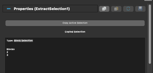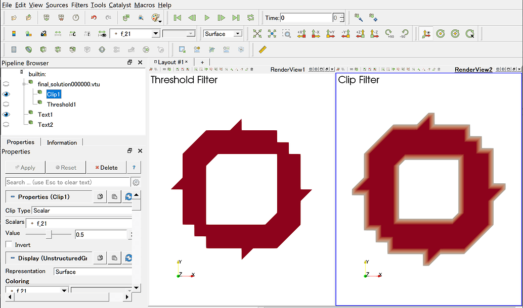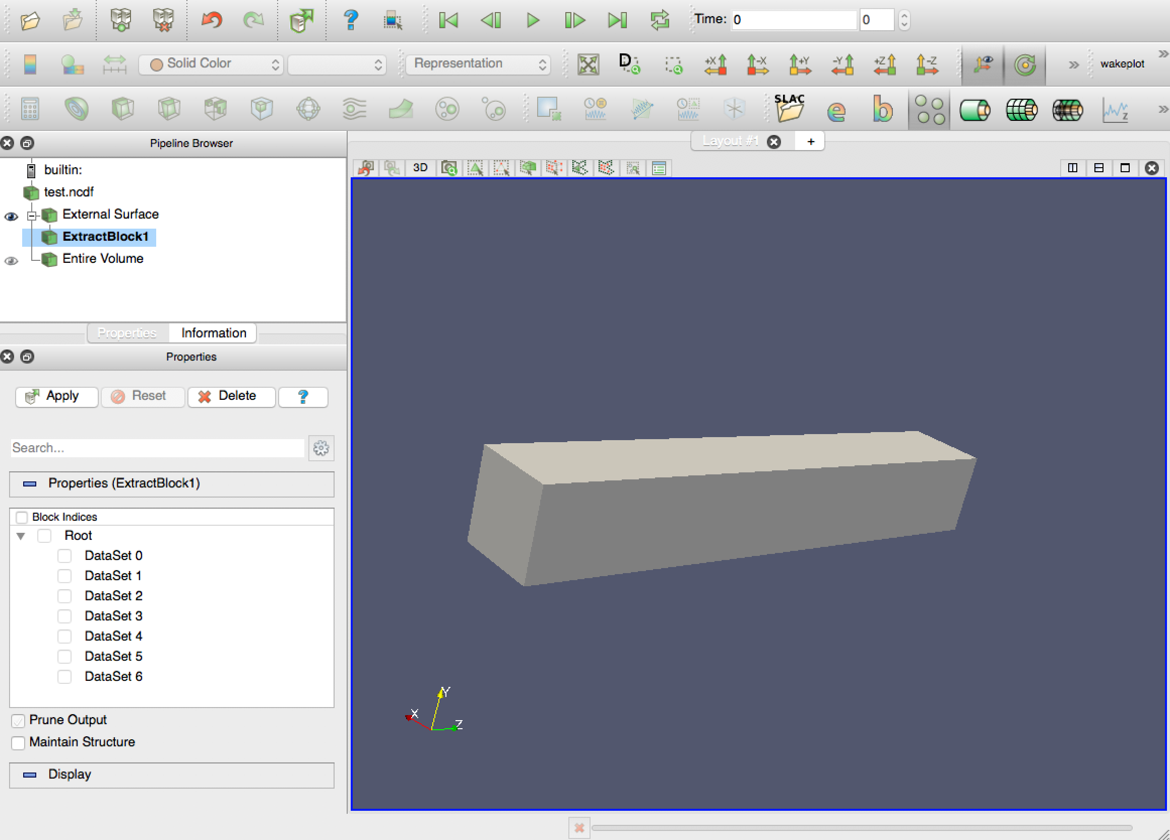

Now, the steps are the same as all other contour operations. For information, when looking for the python version of an interface action you can use the Trace ( Tools/Start Trace ). In this chapter, we take a closer look at various ways of selecting data in ParaView and making use of these selections for data analysis. 1 Answer Sorted by: 3 clip1Display.RescaleTransferFunctionToDataRange (False, True) is the line you want. 1600×902 385 KB This will create a new object in the pipeline browser. B: Click Find Data to perform the selection C: Click Extract to create a new object in the pipeline.

At this point, we are ready to create a contour graph of Xcomponent. ParaView data selection mechanisms are designed specifically for such use-cases. Here is your steps visualized: A: Select the data based on your surface ids or any other variable that defines them. Once the mask array is obtained, this filter will either extract the selected ids, or mark those elements as requested. It relies on to compute a mask array from the query expression.

Similarly, Y and Z components can be extracted using jHat and kHat functions, respectively. This module is used by vtkPythonExtractSelection to extract query-based selections. When we click on Apply, a new scalar variable, Xcomponent is created. This means, that our vector is dotted against the unit vector on i-direction (which means X-axis in our case). When the order is correct, then the command string reads like: iHat.VectorField. The paraFoam script can conveniently be used to select the PVFoamReader (this is the default behaviour), to select the PVblockMeshReader (using the -block option), or to select the native ParaView reader (using the -vtk option).
Then, click on iHat, v1.v2, buttons and select VectorField (or whatever the name you vector field has) under Vectors menu (bottom right-most button). <->First change the Result Array Name to let's say Xcomponent instead of Result. To extract the X component, we perform the following steps. It is listed under the Filters menu and also placed on the far left end of the toolbar. The vector can be decomposed by using the Calculator. For that, the components should be extracted. extractSelection1Display.Representation 'Surface' extractSelection1Display.ColorArrayName None, '' extrac. If you just need to create lines, instead of region to separate the levels, you need to work on the scalars i.e. create a new 'Extract Selection' extractSelection1 ExtractSelection (InputdataVTI, SelectionNone) show data in view extractSelection1Display Show (extractSelection1, renderView1) trace defaults for the display properties. Also, for those of you familiar with Matlab, this operation is like contourf(VectorField,10).


 0 kommentar(er)
